How To Plug In Front Io
Your arrangement will not get-go if you connect the PC case'due south front panel cables to the wrong headers on your motherboard. The connectors that come from the PC case are rather small, and connecting it to one of the pins on the motherboard can exist daunting, especially if you are a beginner.
Therefore, we have brought you this article so you can hands connect the forepart panel connectors to the motherboard, even if yous are doing it for the starting time fourth dimension.
Prerequisites
Before we start, there are a few things to continue in listen before you lot connect the wires to the front console.
- Ground yourself
- If you cannot insert the cables, do not force them in. As the pins are very thin and tin exist aptitude hands.
- Do non turn on your estimator unless y'all are absolutely sure that all the cables are placed correctly.
- Always refer to your motherboard and CPU case user manual if you are unsure about anything.
How to Connect Front Panel Connectors to the Motherboard?
Hither is a footstep-by-step guide on how to connect the front panel connectors to the motherboard.
Find Required Cables From Your CPU Case
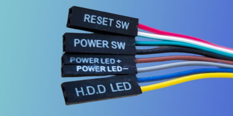
Runway the cables that come up from the forepart console of your CPU case. If you have a heavier CPU example, in that location volition be more cables than this. Here is the list of all front panel cables and how to observe them.
- Power button cable: says POWER SW at the end of the cable.
- Reset button cablevision: says RESET SW at the cease of the cable.
- Ability Led lights indicator cable: this volition have a + and – sign at the end of the cable.
Example: ability led is POWER LED+ and POWER LED- or it tin can be Power LED
- Hard disk led indicator: this wire says H.D.D. LED+ and H.D.D. LED- or H.D.D. LED at the end of the cablevision.
Search Your Motherboard for Forepart Panel Headers
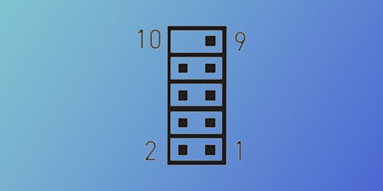
Search for writings similar F_PANEL, JFP1, or FP1 in your motherboard. These writings may be different depending on the motherboard you use. Please refer to the user's transmission if you have issues finding the front panel header. If you don't have a user transmission, use the motherboard manufacturer'due south official support folio to download the manual.
The user manual will have a detailed diagram of the board. Utilize this to locate the front console header.
Your motherboard will also have a JFP2 or SPK1. This is used to connect a speaker cable from the CPU example.
Detect the Positive and Negative Sides of the LED Cable
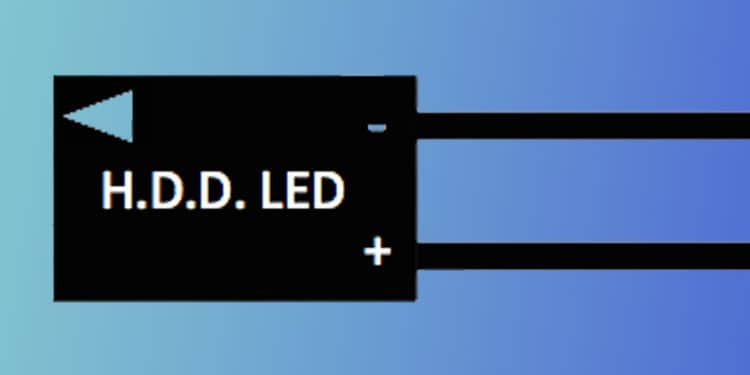
Front end panel cables such as the power and the reset button accept no polarity (positive and negative signs). Then, you can insert them in any manner. In case of LED connectors, y'all should insert the positive terminate of the front console cablevision in the positive pin on the front panel header.
POWER SW and RESET SW volition have two slots in the cable you need to insert into the front console headers. On the other paw, the LED may have one or two slots depending on the CPU case manufacturing company.
If the LED cables say LED+ or LED-, you can easily insert the wires by following the steps explained below. Withal, if the cables only say Power LED or H.D.D. LED, you should effigy out the positive and negative slots first.
You can see a small triangle on the backside of the LED cables. This indicates the positive end, and the another will be negative.
Connect Your Cables
There volition exist 2 sets of pins on your motherboard to connect it to the front panel. One set of pins is called F_PANEL/JFP1/FP1, which holds power, reset, and LED cables. The other i is for the speaker/buzzer, which is chosen JFP2/SPK1.
Connect F_PANEL/JFP1/FP1
There will be nine pins in your front end console header on your motherboard, as shown below.
Brand sure that the pin says "JFP1" or "F_PANEL" Your motherboard will likewise have these numbers written to identify the pins. The pin on one side is odd-numbered, and the pin on the other side is even-numbered. One pin on the meridian of the even side volition be missing.
Apply the post-obit guide to insert your front panel connectors.
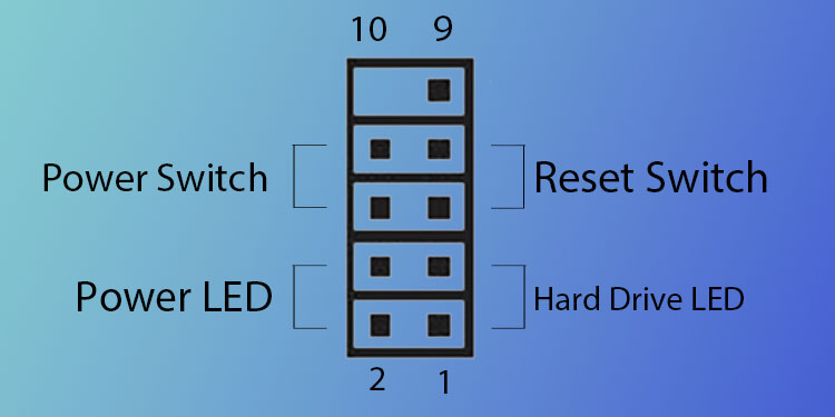
- Pin 1 and 3 are for H.D.D LED+ and H.D.D LED- respectively.
- Pin 2 and 4 are for Ability LED+, and Power LED- respectively.
- Pin 5 and vii for RESET SW.
- Pin 6 and 8 for Power SW.
- Pin 9 will be empty.
The LED lite on the front panel volition non plough on if you lot have not matched the positive pins with positive slots and negative pins with negative slots. Y'all tin invert and reconnect them if the LED does not turn on.
Connect JFP2/SPK1
This cablevision comes with the motherboard and not the CPU instance. It connects to a small speaker, which beeps error codes. JFP2/SPK1 contains one set up of four pins, as shown in the image below.
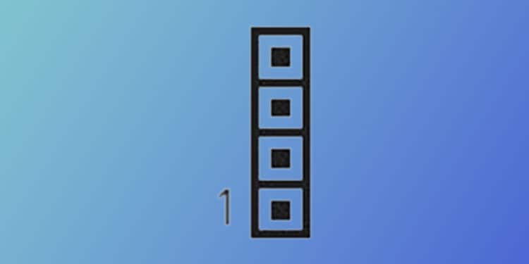
Figure out the positive side of the speaker/buzzer cablevision. The positive slot goes on the fourth pin.
Related Questions
How to Connect Front Panel USB Connectors?
You tin find USB pins on your motherboard. They volition have the give-and-take USB written nether them. Depending on the manufacturer, USB pins may be indicated every bit JUSB1 or F_USB.
If you cannot locate them, please refer to the user manual for your motherboard. I fix of USB connectors will have ix pins on them.
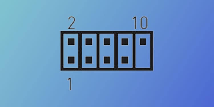
Now, observe the cable from your CPU case that says USB at the end. That cable will have a slot for nine pins. To insert, align the pins and cable and gently insert the connector to the header.
How to Connect the USB three.0 Front Console Connector?
Unlike USB 2.0 pins, a USB 3.0 front console header will accept xix pins on them. This can be located from the JUSB2/F_USB3.0 written near them. To find the cables, check for cables with the color bluish at the terminate, with 20 slots.
A small rectangular wall-like structure volition surround the pins. On one of the longer sides of the wall, there will be a small gap. To insert the cable, marshal this gap with the pocket-sized bulge on the cablevision.
How to Connect the Front Console Audio Jack to the Motherboard?
To find the front panel sound connector, search your motherboard for JAUD1/F_AUDIO. This connector will have a slot for ten pins, five on each side, but pivot number eight will be missing.
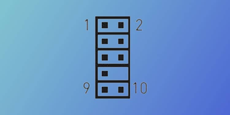
Search for the HD Sound cable from your CPU case. The end of this cablevision volition besides have holes/slots for ten pins, v on each side.
The connector from the example will have i pivot slot missing. Align the pins and the cable so that they fit perfectly.
Source: https://www.technewstoday.com/how-to-connect-front-panel-connectors-to-the-motherboard/

0 Response to "How To Plug In Front Io"
Post a Comment